British Airways flight BA 38 accident and Aircraft Jet A-1 fuel System - part 5
British Airways flight BA 38 accident and Aircraft Jet A-1 fuel System - part 5
This is in continuation of "British Airways flight BA 38 accident and Jet A-1 fuel temperature - part 4" a blog series for understanding Aviation turbine fuel’s role in modern civil flights specially behavior of water in fuel to mitigate it’s adverse effects during flight, including at high altitude where water will turn into ice.
From fuel supplier’s perspective, it is interesting to know the aircraft fuel system which handles water (sumps in tanks, water scavenger pumps), removes external impurities from fuel (strainers-filters), fuel temperature indicators, fuel heater etc.
An aircraft fuel system enables fuel to be loaded, stored, managed and delivered to the propulsion system of an aircraft. Fuel systems differ greatly from aircraft to aircraft due to the relative size and complexity of the aircraft in which they are installed. In a modern, multi-engine passenger or cargo aircraft, the fuel system is likely to consist of multiple fuel tanks which may be located in the wing or the fuselage (or both). Each tank is equipped with internal fuel pumps and has the associated valves and piping to feed the engines, allow for refuelling/defueling, also tanks have fuel jettison system, quantity metering, sensors for displaying fuel related data to crew etc.
The Boeing 777 is a family of long-range wide-body twin-engine jet airliners developed and manufactured by Boeing Commercial Airplanes. It is the world's largest twinjet and has a typical seating capacity of 314 to 396 passengers, with a range of 5,240 to 8,555 nautical miles (9,704 to 15,844 km). Commonly referred to as the "Triple Seven", it’s distinguishing features include the largest-diameter turbofan engines of any aircraft, long raked wings, six wheels on each main landing gear, fully circular fuselage cross-section and a blade-shaped tail cone. Developed in consultation with eight major airlines, the 777 was designed to replace older wide-body airliners and bridge the capacity difference between Boeing's 767 and 747. As Boeing's first fly-by-wire airliner, it has computer-mediated controls. It was also the first commercial aircraft to be designed entirely with Computer-aided design.
The 777 is produced in two fuselage lengths as of 2017. The original 777-200 variant entered commercial service in 1995, followed by the extended-range 777-200ER in 1997. The stretched 777-300, which is 33.25 ft (10.1 m) longer, followed in 1998.
The 787 Dreamliner which entered service in 2011, shares design features and a common type rating for pilots with the 777.
 |
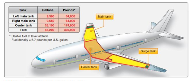
| Fig-1, Boeing 777 -200ER fuel tanks capacity and position |
The fuel System
The fuel on the Boeing 777-200ER is stored in three fuel tanks: a centre tank, a left main tank and a right main tank (see Figure2). The centre tank contains two override / jettison pumps (OJ) and each main fuel tank contains two boost pumps, identified as forward and aft. Each of the pump inlets is protected by a ¼ inch mesh screen and the pumps are equipped with a check valve fitted in the discharge port, to prevent fuel in the fuel feed manifold flowing back through the pump
 |
| Fig-2, Boing 777 - Simplified Diagram of the Airframe Fuel sysytem |
Fuel feed manifold
The fuel feed manifold runs across the aircraft and connects to the engine fuel feed lines. The manifold is split between the left and right system by two cross-feed valves, identified as forward and aft. The fuel from the left and right main tanks supplies their respective engines during main tank feed.
Fuel tank vent system
Each tank is vented to atmosphere through channels in the roof of the fuel tanks, which are connected to surge tanks mounted outboard of each of the main tanks. The surge tanks are vented to atmosphere through a flame arrestor and a scoop mounted on the lower surface of each wing.
Fuel delivery
If fuel is loaded into the centre tank, the normal operation is to select all OJ and boost pumps on at the start of the flight. As the OJs operate at a higher delivery pressure than the boost pumps the centre tank will empty first. During this period the boost pumps will provide fuel flow for their internal cooling and lubrication and supply motive flow to the jet pumps. When the centre tank is nearly empty, the pressure in the fuel feed manifold reduces and the main tank boost pump check valves open, supplying fuel into the manifold.
The aircraft is equipped with a centre tank fuel scavenge system, which increases the amount of usable fuel in this tank.
Water scavenge - Each tank has water scavenge pumps that operate continuously
To prevent large amounts of ‘free water’ building up in the fuel tanks, the aircraft is fitted with water scavenge system. One jet pump is located in each main tank and there are two in the centre tank. In the main fuel tanks the jet pumps draw fluid from the lowest sections of each tank and inject it close to the inlet of each aft boost pump. In the centre tank, fluid is drawn from the lowest section of the tank and injected close to the OJ inlets.
Centre tank fuel scavenge
Engine low pressure stage of the Main Engine pump (Figure 3)
The airframe fuel system supplies fuel to the LP engine-driven pump, which forms part of the Main Engine Pump (MEP). This raises the fuel pressure (and fuel temperature slightly) and pumps the fuel through a Fuel/Oil Heat Exchanger (FOHE).
 |
| Fig-3, Boin 777 Simplified diagram of the Engine Fuel system |
Fuel Oil Heat Exchanger (Figure 4)
The FOHE serves the dual purpose of cooling the engine oil and raising the temperature of the fuel so that ice does not affect the downstream components, including the LP filter and the Fuel Metering Unit (FMU). The FOHE is a hybrid cross-flow / counter-flow design and it includes a matrix of fine tubes. The fuel enters the top of the FOHE and passes through the tubes; the hot oil enters the FOHE main body and passes around the fuel tubes.
The temperature of the fuel after it has passed through the FOHE is considerably above its entry temperature. The FOHE matrix consists of over 1,000 small tubes that are crimped at various locations along their length to improve thermal transfer efficiency.
 |
| Fig-4, Fuel Oil Heat Exchanger ( FOHE ) |
Engine burners and fuel flow meter ( Figure 3)
The fuel from the FMU is routed to the burners via a flowmeter and a coarse HP strainer.
In summary look for fuel tanks, pumps, filters and fuel heater to ensure proper fuel management with control on adverse effects of water.
In next part, we will see fuel Quantity aspects during the flight.
Author's Profile
List of all blog articles on Petroleum QC by RJ Patel.
References:
Report on the accident to Boeing 777-236ER, G-YMMM, at London Heathrow Airport on 17 January 2008
- Wikipedia https://en.wikipedia.org/wiki/British_Airways_Flight_38
Chapter 14: Aircraft Fuel System - FAA
Earlier parts of this series:
British Airways flight BA 38 accident and Jet A-1 fuel temperature - part 4
British Airways flight BA 038 flight altitude and Cold fuel Management - part 3”
British Airways flight BA 38 accident and Jet A-1 fuel temperature - part 4
British Airways flight BA 038 flight altitude and Cold fuel Management - part 3”

Comments